|
|
The cooling fan and heatsink are referred as "Thermal module" in Acer official documentation ( Part # 60.FR7V5.003). I found the exact match at Laptop Repair
Tools needed:
Note Screws for different components vary in size and it is highly recommended to group them with the corresponding components during disassembly procedure to avoid mismatch when putting them back in place
Before you begin free your body of any electrostatic charge you might have accumulated - touch a metal ground or metal water pipe.
Make sure the system is powered off, power adapter is unplugged and battery pack is removed from the laptop.
1. Turn your laptop upside down
2. Slide the battery lock

3. Slide the battery latch, release battery and remove it

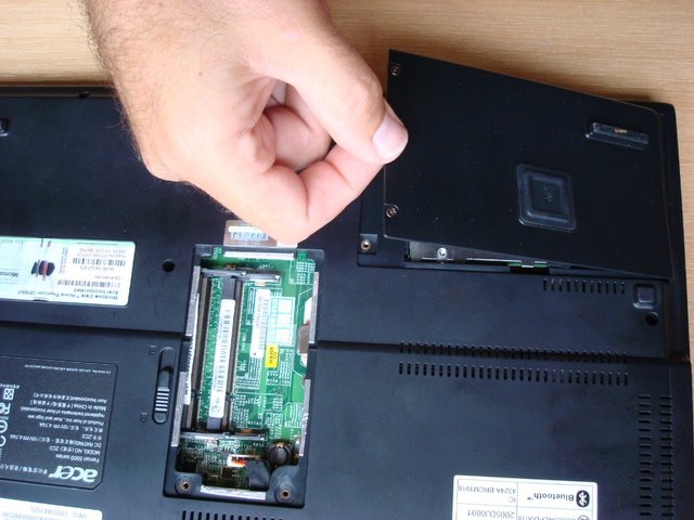
1. Release 2 screws fastening the DIMM cover

2. Remove the DIMM cover

3. Pop out the memory modules (please, do not touch metal parts of the modules)

and remove the modules one by one.

1. Release the 2 screws holding HDD cover

2. Detach the HDD cover from the main unit

3. Remove the screw fastening the HDD module

4. Disconnect hard drive and pull it outwards using the strap

1. Release 2 screws fastening the wireless cover

2. Remove the wireless LAN card cover

3. Disconnect the wireless antenna (notice each cable color to properly connect the antenna back)

4.Remove the 2 screws holding the wireless LAN card

5.Take out the wireless card from the socket

1, Release the ODD latch as shown

2. Detach the optical drive from the main unit

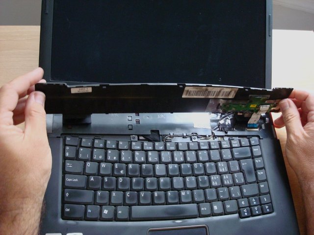
1. Remove the two screws fastening the middle cover and place it as shown

2. Open the laptop as shown.

3. Then detach the middle cover (could be easily done with your finger nails from both sides)

and turn it as shown

4. Disconnect the launch board cable from the main board. First lift the black cable lock then carefully pull up the ribbon-like cable.

5. Remove the middle cover (with launch board and launch board cable) and put it away

6. Remove the 2 screws fastening the keyboard

7. Turn over the keyboard and place it as the image shows

8. Disconnect the keyboard cable from the main board

then remove the keyboard

9. Disconnect the microphone cable and the touchpad board cable from the main board

10. Disconnect the LCD cable from the main board

11. Take out the microphone cable from the upper case

12. Pull out the wireless antenna cables from the back side

13.Remove the four screws holding the LCD module

14. Detach the LCD module from the laptop

1. Remove the 8 screws holding the upper case and the lower case assembly on the front side

2. Remove the 15 screws fastening the upper case and the lower case assembly on the bottom side

3. Turn over the main unit and disconnect the bluetooth cable from the main board

4. Disconnect the power board cable from the main board on the bottom side

5. Carefully detach the upper case assembly from the lower case assembly

1. Disconnect the USB cable from the main board and detach the cable from the lower case

2. Press the dummy PC card button and remove the dummy PC card

3. Detach the dummy expand card from the lower case

4. Tear off the mylar fastening the modem cable and disconnect the modem cable from the modem board

5. Remove the two screws holding the modem board

6. Disconnect the modem board from the main board

7. Disconnect the speaker set cable from the main board

8. Remove the two screws fastening the main board assembly to the lower case

9. Cautiously take out the main board assembly from the lower case


12. Turn the main board upside down
13. Remove the 5 screws fastening the thermal module to the main board and disconnect its cable

14. Disconnect thermal module cable

15. Take the termal module out

Reverse the procedure for assembling your laptop with your new cooling fan.
This article could be a base for at least several more 'howto'-s such as "Acer Ferrari 5000 - How to replace keyboard" and "Acer Ferrari 5000 - How to replace RTC / CMOS battery", as well as to replace other components: wireless LAN card, LCD module, modem, memory, hard drive etc.